Environmental Solutions.
Redefined.
Empowering industries to create a more sustainable future.
We deliver environmental solutions that are redefining the emissions control market.
Conifer Systems provides cost-effective, state-of-the-art systems and services. Our solutions maximize uptime and increase operational efficiencies across all industries.
Conifer Systems empowers companies to decrease their carbon footprint while keeping emissions at bay.
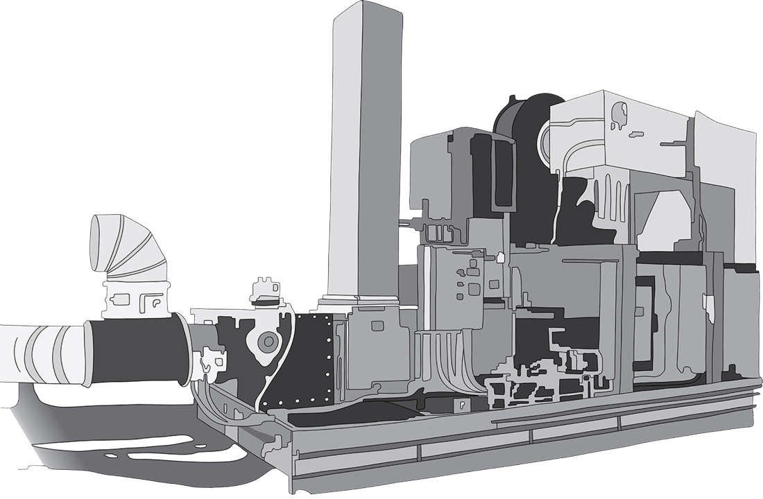
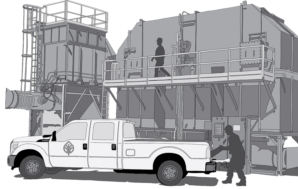
Emissions Control Systems
We design and manufacture high-quality oxidizer, scrubber and carbon adsorber systems for reliable, efficient and cost-effective emissions control.
Our experienced team of applications engineers is here to develop the ideal solution for your emissions control needs.
Aftermarket Services
We offer a full suite of aftermarket services, from system installation and commissioning, to preventative maintenance and process optimization services.
We also offer rental systems and emergency abatement services.
Our team of highly-trained aftermarket technicians is available 24 hours a day, 365 days per year.
500+
Environmental Solutions
30
24/7
Regulations and emissions standards are dynamic. This is why our approach is both proactive and agile. Conifer Systems can develop a custom solution to tackle your specific emissions problem.
Our team will prioritize your needs, delivering reliable, efficient and cost-effective solutions while adhering to the highest quality service.
“For more than 45 years the Clean Air Act has cut pollution, as the U.S. economy has grown. Between 1970 and 2020, the combined emissions of the six common pollutants dropped by 78 percent. This progress occurred while U.S. economic indicators remain strong.”
Let’s continue on this path together.
“The Clean Air Act requires that when new industrial facilities are designed and built, good pollution control must be part of the design. This means that as new, cleaner facilities are built, the country’s industrial base becomes cleaner overall. Public health is protected as economic growth proceeds.”
Conifer Systems can help you get there.
How We Do It
With in-house development and manufacturing, we are well-positioned to meet your emissions control needs.
From solution development to manufacturing and installation and commissioning, Conifer Systems will work together with you to deliver a reliable, efficient and cost-effective emissions control system.